A maze of wiring and electrical accessories is hidden by the smooth exterior of an aeroplane
NO JOINTS ARE PERMITTED in the wiring of an aeroplane. Junction boxes are used in all instances where one connexion has to join another, the ends of the wires being held by terminals. The photograph shows one of the engine-control junction boxes on a De Havilland Albatross aircraft. The girder supports for the engine may be seen to the right of the junction box, running up from the wing.
AN aeroplane of today may have four or more generators, two or more batteries, and half a dozen motors for the lifting and lowering of retractable undercarriages or the movement of gun turrets, flaps, and trimmers. It may have, as well, motors to drive petrol pumps or high-voltage generators for use with radio.
Among the batteries there will be a large-capacity one for starting the engines; each engine being fitted with its own electrical starter. The drain on a battery may be as much as 150 amperes for each starter; this gives an indication of the size and weight of cables required. Sometimes there is, in addition, a little battery for the filament current of wireless valves.
The electric lamps on an aeroplane serve many purposes. In the nose there may be a double-filament landing lamp of high candle power. Sometimes there are two landing lamps, one on either wing. Navigation lights are placed at the tail and on either wing (see the chapter “Traffic Rules of the Airways”). Cabin lighting must be sufficient for passengers to read in comfort. Instrument board lighting must be of such a type that it can be bright when the-aircraft is flying high or dimmed so as not to dazzle the pilot when landing in the dark. As well as all these, many aircraft carry on the underside, for use as a downward identification lamp, a signalling light connected to a Morse key.
Where it is not convenient to use bulkhead or roof lamps, small spot lights may be fitted to illuminate instrument switchboards, the instruments which are essential to the pilot in making a landing in the dark, or any part of the aircraft accessory equipment which may require attention during flight, especially in the dark.
Electricity has been applied to certain of the instruments. One of the best known types of fuel gauge depends upon the alteration of voltage in a circuit connected to a slider on top of the tank,
and moved by a float ascending a spiral channel. Wires must therefore be run from this movement in each tank to an indicator; this is, in effect, a small voltmeter or milliammeter on the dashboard. These wires do not go direct to the indicator, as a single indicator may be supplied for a number of tanks. The wires are connected to a small changeover switch which connects each circuit in turn to the indicator dial mechanism.
Revolution indicators for multi-engined aircraft are almost always of the electrical type. Each engine nowadays drives a tiny dynamo or alternating current generator with a voltage directly proportional to the speed of rotation. It is therefore possible to calibrate a voltmeter dial to indicate revolutions instead of volts, one dial being supplied for each engine.
To avoid congestion of the dashboard by having as many as four dial-type engine revolution indicators in a row, the pointer for each instrument may move over a scale set edgeways. Several such scales can be installed side by side in a small space. The advantage of this is that the pilot can see at a glance whether or not all the indicating needles are in line. This shows that the revolutions per minute are all in step.
The control of several generators, a number of motors, a motor generator, one or more batteries and a large number of lights necessitates switchboards and fuseboards. These will be complex if not large. In addition to these, there will be a special type of voltage regulator for each generator, to prevent the voltage from rising to dangerous heights should the speed of the aircraft be greatly increased.
Each generator is driven either from one engine, which may be running at high speed during a steep dive, or from a small wind-driven propeller. The speed of the propeller will be high in a dive or steep glide. This would cause strain on the insulation and lamps, as well as overcharging of the battery, were it not for the voltage regulator. The voltage regulator compensates for voltage variations up or down, the variations depending upon variations in the speed of the engine or of the aircraft. As with all battery charging, a cut-out is required in the generator circuit. This cut-out is similar in appearance and construction to that used on any modern motor car. It prevents the accumulator from discharging through the generator when the voltage falls, and automatically closes when the generator voltage reaches that required to charge the battery.
The Landing-Light Switch
Most of the switches are of the normal type; at least one is of special construction, that for the double-filament lamp in the nose or out on either wing for landing purposes. It is essential that both filaments shall not be switched on at once, otherwise too much heat would be generated. The switch is therefore designed to permit only one filament to be connected to the supply at a time. Either a high-voltage filament or a low-voltage filament may be in circuit, but-not both.
There are, in addition, the usual wiring sundries: plugs and sockets, terminal blocks and fuses. Among the sockets will be one on the underside of the front of the fuselage connected to the
electric motors which start the engines. When an aeroplane is starting, either from its own aerodrome or some large airport, there is no reason why the engine starting should be carried out by its own battery and thus use up current which might be needed later for unexpected starts, for night landing or for other purposes. Aircraft are therefore frequently started by a powerful battery, wheeled about on a small trolley. The battery is plugged into the socket fixed for this purpose on the underside of the fuselage. Each engine can be started in turn by its own starter button provided that a throwover switch has been incorporated which will disconnect the aircraft battery and connect up the starter buttons to the external plug.
TWIN FILAMENT BULBS are used in landing lights which may be mounted in the nose of the aircraft or on the wings. Three wires run from the lamp to a two-position switch which enables a quick changeover to the second or stand-by filament should the normal filament fuse. The second filament is of lower voltage rating than the normal one so that it may be fitted into the limited space available in the bulb and yet be correctly in focus.
In military aircraft there is one other type of electrical equipment which will in all probability not be necessary for air liners. Open aircraft, of the type used for fighting, may require to fly at such a great altitude that the extreme cold would render the pilot incapable of perfect control of his machine, good navigation, or of carrying out an active offensive upon any enemy aircraft or formation. Electricity is used therefore to heat clothing. A suit with asbestos lining is fitted with resistance wires which will heat up to a particular temperature, and then remain heated with no further temperature increase. The wires are run back and forth in the fabric of a suit which covers legs and body. There are separate connexions on the legs and arms to carry the current to boots and gloves.
On the breast pocket of such a suit there is a small plug from which a connexion can be carried to goggles, in which one or two fine resistance wires pass from side to side of either eye piece. This prevents mist on the glass from freezing and thus obscuring the pilot’s view. If water-cooled machine guns are used, there will be a heater circuit for these also.
Such aircraft carry a small additional switchboard, lettered “Hands, Body, Feet, Guns”. This switchboard is provided with four switches, so that the current to any one of the components of an electrically heated suit, or to the guns, can be switched on or off at the discretion of the pilot. When so much equipment has to be installed in an aircraft, special methods of wiring must necessarily be adopted.
The voltage is low; batteries are generally of the 14-volts type, although this voltage may eventually be doubled for large liners and the largest types of military aircraft. The low voltage necessitates heavy cables, especially where the large consumption of current by an engine starter has to be taken into account.
No joints in cables are permitted. Instead, every junction is made at a terminal block, on which each incoming cable is connected to a terminal, and from which the continuation cable, connected to another terminal on the same block, starts out on the completion of the circuit. For example, it may be necessary to carry cables from the generator to a navigation lamp, not taking into account intermediate items of equipment, such as fuses and switches. The generator cables will be connected to a terminal block and the outgoing supply cables will be connected to a corresponding set of terminals joined at the back of the block to those to which the generator is connected.
When Wings are Removable
If the aircraft is of the type in which the front fuselage is capable of being disconnected from the remainder, the supply cables will come up to another terminal block at the break; if the wings are removable, there will be a terminal block at that junction also.
Furthermore a connexion is never made direct to any item of equipment which may need occasionally to be removed. Direct connexion would mean that the wiring itself would have to be jointed at some place'or removed with the lamp or instrument in question. To overcome this, the cable is led to a small terminal block against, for example, the wing lamp, and connexions
from the lamp are made to the opposite side of the block.
All cables are provided with cable lugs. Where solder is used in the fixing of these lugs a non-corrosive flux must be used consisting only of resin or resin dissolved in methylated spirit. Although the soldering is then perfectly safe from corrosion, the last inch or more of the cable, at the point where it is connected to the lug, will be slightly more brittle than in the remainder of its length.
If at that brittle portion a breakage were to occur, the whole length of the cable would normally have to be withdrawn and substituted. It is therefore usual to leave a small loop providing an inch or more of spare cable at the point where junction to a box is made by a soldered lug.
MANY TYPES OF CABLES, varying in size according to the amount of current to be carried and the voltage required, are used in the wiring of an aircraft. The cables are often laid in light aluminium channels or ducts which are sometimes provided with lids. Cross-pieces are used to hold the cables in position and to bond their braided metal coverings together.
Cables are often laid in light aluminium channels or ducts, sometimes provided with lids. Whether there is a lid or not, cross-pieces serve not only to hold the cables in place, but also to bond their metal braiding where they are of the screened type.
Cables must be laid in the ducts in a single layer only, and it is necessary to keep different services apart. Light, heat and power might reasonably be run in a single duct, but radio services and intercommunication or internal telephone lines would be segregated. Both must be separate from any ignition circuits. This is of importance where engines and tanks may be out on the wings — an arrangement necessitating wing generators and a large number of connexions to junction boxes at the wing roots, in addition to the junction box within the fuselage.
An aircraft is, among other things, a wireless station. But as such it will not be a success unless some means are adopted to minimize the interference due to the sparking constantly taking place at the sparking plugs. Not only does this sparking directly emit disturbances which would be taken in by a radio receiver, but also the disturbances
are transmitted along all wires connected to the blocks. To screen this emission and isolate it as far as possible, the plugs are hooded and the cables are covered with metal braid, the braiding being earthed and every wire cross-connected to adjacent braiding. This process is called screening.
Most modern aircraft are of the all-metal type, though some passenger liners are made with plywood structure. Whichever type is being built, it will be necessary to ensure electrical connexion between the different metallic parts. Metal fittings in wooden aircraft must all therefore be bonded together. Even where one metal fitting joins another it is usual to connect a small cable from one to the other to ensure that the electrical resistance at the junction is invariable. A varying resistance might cause a varying earth current, with interference in radio services.
When so bonded together, the whole of the metal parts of an aeroplane form an earth or, since they are all insulated from the earth proper, a counterpoise to the aerial.
The aerial may be of the trailing type; then it passes through a tubular insulator, and trails below the aircraft. Or a short aerial may be run from posts set up at front and rear of the fuselage, or the aerial wire from wing tips to tail. The latter method is sometimes adopted in fighting types of aircraft.
Cleating of cables, especially heavy cables, occurs at frequent intervals. As a rule cleats are not more than 12 in. apart at a maximum and may be 8 in. apart where it is considered necessary. Under each cleat a small piece of insulating material is slipped, except where the cleat is used in a duct to bond the braiding of several cables together. It is advisable to have one cleat as close as possible to a junction box or terminal block, to prevent any pull from coming on to the conductors at the connexions to the terminals, and also to maintain in place the small loop of spare wire when lugs are soldered.
It is essential that single cables, and particularly those carrying heavy currents, should not pass close to the magnetic compass, lest deviation or variation of its readings should occur.
The effect of induction from the lighter cables can be overcome by twisting them together; but the plan of the aircraft should ensure that heavy cables are kept at a considerable distance from the compass. This instruction applies particularly to the placing of the wiring of equipment which embodies magnetic coils, especially solenoid switches.
A whole series of special types of cables has been developed by the Cable Makers’ Association and the Air Ministry in cooperation, solely for use in aircraft. Both in specifications issued by the Directorate of Technical Development at the Air Ministry, and in the specification issued by the British Engineering Standards Association, these types are listed and given names which to some extent identify them with their sizes and structure.
WIND DRIVEN OR ENGINE DRIVEN GENERATORS may be used on aeroplanes. A wind driven generator is turned by a small windmill mounted in the slipstream from the propeller, while the engine driven type is mounted directly on to the engine casing and driven mechanically. A generator with twin outputs is shown in the lower part of this photograph, and a starting motor can be seen on top of the engine, which is of the inverted type.
The glazed, cotton-braided, flexible cords and cables are all named in such a way that their flexibility is identified by their nomenclature. For example, “Uniflex 4” is a flexible cable of this type with a single conductor, and intended to carry 4 amperes under the Institution of Electrical Engineers Wiring Rules. It is unnecessary to explain “Duflex 37”, “Quintoflex 7”, or “Nonoflex 4”; and reference may be made to the multicore cable styled “Twensevenflex 2”.
Where cables are sheathed, a similar nomenclature is adopted. “Unisheath 19”, “Trisheath 7” and “Quintosheath 4” speak for themselves; and reference may be made to such combinations as “Triflat”, which is a 3-core cable with the conductors laid side by side, or “Unistart”, which is a single-core cable used for heavy current starters. “Unistartal” is the same type of cable with an aluminium core instead of a copper core. Cellulose covered cables are styled “Unicel” and “Ducel.”
Some types of instrument have a small lamp set in the rim. This lamp is much smaller than a pea, and little larger than a good-sized grain of wheat. The lamp naturally requires conductors, and a special type of flexible cable has been evolved for this purpose; it is styled “Instruflex”.
With such a multiplicity of cables, confusion is avoided as far as possible by distinctive colouring of the finishing layer. Such colourings are universally allotted to certain services. Electrical ignition circuits use flexible cables in which the final covering is coloured blue. Those for wireless have a red outer covering, those for general heating and lighting yellow, and those for retractable undercarriage indicator services a grey covering.
In Royal Air Force aircraft the release gear for bombs may be operated electrically, and the cables used for this purpose in Service aircraft are white. Cables for internal telephone service, as from one position in an aircraft to another, are green.
Colour is not used solely to distinguish between the services for which wires have been run; a series of colours has also been laid down for the wrapping of the rubber next to the conductor itself.
A red core is used for a positive lead, and a blue core for a negative one. If there are any more cores they are green, yellow, white, black and slate. Multi-core cables above this number use combinations of colours specially laid down, red and blue for the 8th core, blue and black for the 17th, blue, red and yellow for the 30th. The foregoing description provides an outline of the general methods of wiring applicable to aircraft as distinct from the more familiar types with which a house electrician would deal. It remains to consider the various classes of electrical equipment and the special precautions which are necessary in their installation and connexion.
The most important item of equipment is the generator. Generators are of two types, those driven from the engine, suitable for outputs as large as 1,000 watts at 24 volts, and those intended for drive by a small propeller, the generator being mounted in the leading edge of the wing.
Interposed between the generator and the battery there will be the control box or voltage regulator, and the battery cut-out, which prevents a reversal of current at a time when
the generator speed is such that the generator volts do not equal the battery volts. Both at the generator end and for connexions to any intermediate component a standard type of terminal block will be used. At the battery end there is provided also a dummy block with one set of terminals and no outgoing connexions. When the battery has been taken away for external charging it is inadvisable for connexions to be left hanging loose and the wires that normally go to the battery are then screwed down to the dummy block.
WIRING IN THE COCKPIT has to be kept clear of the compass as far as possible. Single wires must never run near the compass because electro-magnetic induction from them may cause incorrect readings of the aircraft’s bearings to be obtained. Induction may be overcome with thin wires of the same circuit, by twisting them together so that their electro-magnetic fields are cancelled out.
Aircraft batteries are of the lightest possible construction consistent with the use to which they are subjected. For many years a non-spillable type has been in use in military aircraft so that, should the aircraft be flying upside down while carrying out aerobatics, the battery acid or alkali will not run out. Service use has provided a prolonged test of a device intended to make batteries unspillable; and in air liners the unspillable design of battery is now in general use instead of the semi-unspillable type.
The majority of batteries in aircraft to-day are still of the lead-acid type used for so long on motor cars. For tropical use where, to the high temperature induced by charging there may be added a high air temperature, it has been found that the alkaline type has a longer alkaline battery has been extensively applied to Service aircraft for some years and is now coming into use also for air liners, especially Imperial Airways long-distance passenger aircraft. The plates are nickel-iron working in an alkaline solution, or, alternatively, nickel-cadmium.
The heaviest load on the batteries and, therefore, on the largest size of cable connexions will be caused by the use of one or more engine starters. It is usual to put in a larger size of battery as well as a larger size of generator should the engine be electrically started.
It does not follow that the heavy cable between battery and starter must necessarily pass through the pilot’s cockpit, although the engines must be started by the pressure of a button on or close to the instrument panel.
This detour is obviated by the use of what are termed solenoid switches. When the pilot presses the starter button he closes a circuit of light wiring and small current, which terminates in a magnetic solenoid operating a plunger switch. The small current, multiplied magnetically by the many turns of the solenoid, operates the plunger and closes the main circuit for the heavy current flowing from battery to starter. The solenoid switch will normally be as close as possible to the starter motor; it may even be bolted on to the same bracket.
The engine starter has an electric motor taking a heavy load from the battery. In modern aircraft there may be smaller motors for the operation of auxiliary services, including raising and lowering of the undercarriage, movement of gun turrets, operation of petrol pumps and windscreen wipers, and the operation of flaps and trimmers.
A small type of motor has been specially designed for this purpose. For most uses it is provided with a split field system, two series fields being wound in opposite directions. The winding of this field system in conjunction with two solenoid switches renders the motor reversible without the need for a heavy duty reversing switch.
Although solenoid switches are developed primarily for engine starting requirements, they can be used for the operation of small motors such as these. The equipment comprises the solenoid switch mounted as close as possible to the motor to be served and a special type of push button in the cockpit, sometimes shrouded as a precaution against accidental operation of the switch.
The landing lamp, requires special installation. Its efficiency depends on its position and on the ease with which it can be controlled by the pilot.
Landing lamps may be mounted in the nose of the aircraft, but they are sometimes fitted, in a retractable form, on the underside of each wing and as near each wing tip as possible. The sight line of the pilot is inclined about 15° to the left or right of the line of flight and is parallel to and not along the beam of the landing light.
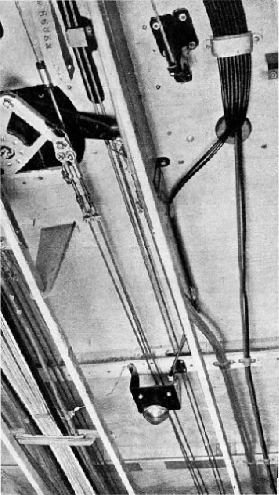
LEADS RUNNING ALONG THE UNDERSIDE of a De Havilland Dragon Rapide. The signalling lamp which points downwards is used to send out in Morse the identification letters of the aeroplane. All metal parts on an aeroplane carrying radio apparatus are joined together electrically. A short wire can be seen running from the left-hand side of the signalling light frame to “earth” it to the braiding of one of the cables on the left of the photograph.
Control cables operate the retractable lamp, by transmitting push and pull loads through dural tubing. Although curves are permissible, no bend should be less than 3 in. radius and there should be as few curves as possible. The conduit must be supported by cleats in a similar manner to the cable. Reference has already been made to the necessity for a special type of switch for this lamp to avoid the danger of having main and auxiliary filaments alight together. The lamp has three leads, black, red and yellow; the red lead supplies the main filament, the yellow the auxiliary filament, and the black is a common return.
Click here to see the photogravure supplement to this chapter.